
| GIS Data |
|---|
| • Creating GIS Data • Types of GIS Data • Types of Error in GIS • What is Metadata? • GIS Glossary |
Digitizing in GIS is the process of converting geographic data either from a hardcopy or a scanned image into vector data by tracing the features. During the digitzing process, features from the traced map or image are captured as coordinates in either point, line, or polygon format.
Types of Digitizing in GIS
There are several types of digitizing methods. Manual digitizing involves tracing geographic features from an external digitizing tablet using a puck (a type of mouse specialized for tracing and capturing geographic features from the tablet). Heads up digitizing (also referred to as on-screen digitizing) is the method of tracing geographic features from another dataset (usually an aerial, satellite image, or scanned image of a map) directly on the computer screen. Automated digitizing involves using image processing software that contains pattern recognition technology to generated vectors. More detail about creating geographic data can be found in this article: Methods for Creating Spatial Databases.
Types of Digitizing Errors in GIS
Since most common methods of digitizing involve the interpretation of geographic features via the human hand, there are several types of errors that can occur during the course of capturing the data. The type of error that occurs when the feature is not captured properly is called a positional error, as opposed to attribute errors where information about the feature capture is inaccurate or false. These positional error types are outlined below, and a visualization of the different methods is shown at the bottom of this section.
During the digitizing process, vectors are connected to other lines by a node, which marks the point of intersection. Vertices are defining points along the shape of an unbroken line. All lines have a starting point known as a starting node and an ending node. If the line is not a straight line, then any bends and curves on that line are defined by vertices (vertex for a singular bend). Any intersection of two lines is denoted by node at the point of the intersection.
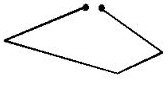
Dangles or Dangling Nodes
Dangles or dangling nodes are lines that are not connected but should be. With dangling nodes, gaps occur in the linework where the two lines should be connected. Dangling nodes also occur when a digitized polygon doesn’t connect back to itself, leaving a gap where the two end nodes should have connected, creating what is called an open polygon.
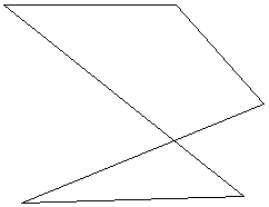
Switchbacks, Knots, and Loops
These types of errors are introduced when the digitizer has an unsteady hand and moves the cursor or puck in such a way that the line being digitized ends up with extra vertices and/or nodes. In the case of switchbacks, extra vertices are introduced and the line ends up with a bend in it. With knots and loops, the line folds back onto itself, creating small polygon like geometry known as weird polygons.
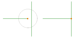
Overshoots and Undershoots
Similar to dangles, overshoots and undershoots happen when the line digitized doesn’t connect properly with the neighboring line it should intersect with. During digitization a snap tolerance is set by the digitizer. The snap tolerance or snap distance is the measurement of the diameter extending from the point of the cursor. Any nodes of neighboring lines that fall within the circle of the snap tolerance will result in the end points of the line being digitized automatically snapping to the nearest node. Undershoots and overshoots occur when the snap distance is either not set or is set too low for the scale being digitized. Conversely, if the snap distance is set too high and the line endpoint snaps to the wrong node. In a few cases, undershoots and overshoots are not actually errors. One instance would be the presence of cul-de-sacs (i.e. dead ends) within a road GIS database.
Slivers
Slivers are gaps in a digitized polygon layer where the adjoining polygons have gaps between them. Again, setting the proper parameters for snap tolerance is critical for ensuring that the edges of adjoining polygons snap together to eliminate those gaps. Where the two adjacent polygons overlap in error, the area where the two polygons overlap is called a sliver.

Summary Visualization of the Main Types of Digitizing Errors
