Due to excessive human activity, an Urban Heat Island (UHI) is a section of an urban or metropolitan area that has a much higher temperature than its rural counterpart. The temperature difference is most noticeable at night and when the breezes are weak.
Urban heat islands tend to affect the social, economic, and physical make-up of the environment. An excessive increase in urban temperature can cause mental and health illness of individuals. An estimation of highly heated spots in urban centers can help in the provision of well-informed futuristic techniques that will address the United Nations’ Sustainable Development Goals 2, 3, 6, 7, 9, 13, 14 and 15.
Using Remote Sensing and GIS Analysis to Determine Urban Heat
This GIS tutorial contributes to the battle against urban heat islands by making use of remote sensing and geospatial science techniques (ArcGIS Pro) to outline procedures that can be followed to assess urban heat in a Region.
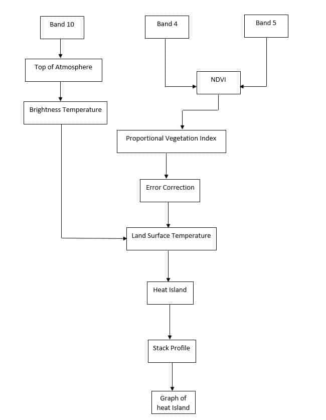
Relevant factors that will be utilized in this tutorial are Normalized Difference Vegetation Index (NDVI), Proportional Vegetation Index, Brightness Temperature, Error Correction, Top of Atmosphere, and Land Surface Temperature.
Figure 1 below shows a summary of the method employed in this tutorial.
Estimation of NDVI from Satellite Imagery
The Normalized Difference Vegetation Index (NDVI) dataset can be accessed freely from the United States Geological Survey (USGS) website after registration. The NDVI can also be calculated using the Landsat toolbox after performing line correction where necessary (Landsat 7 imagery). In order to perform scanline correction with the Landsat toolbox, this video may be useful (https://www.youtube.com/watch?v=kJGkl_Q7D3w). The Landsat toolbox can also be accessed using this link (https://drive.google.com/file/d/1FKc-G1vMVtWXi66hh15VKoj-zk3UPWgX/view).
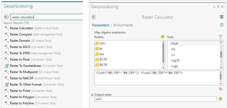
Normalized Difference Vegetation Index can also be performed by using the raster calculator in ArcGIS Pro. In order to use this procedure, follow the steps outline below;
- Open ArcGIS Pro and create a new project. Select blank project from the interface that appears. Select and set output location and name for the new project. Click Ok.
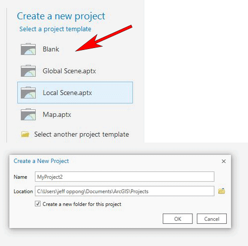
- Import band 4 and band 5 of the Landsat 8 imagery using the “Add data” tool. Set input location and name, and click Open.

- Type and search “raster calculator” from the search bar of the geoprocessing tool.
- From the calculation bar of the raster calculator, type the formula for the estimation of NDVI (“float (band 5-band 4) / (band 5+band 4)”).
- Set Output raster name and location. Click “Run”.
Calculation of Top of Atmosphere (TOA) from Band 10
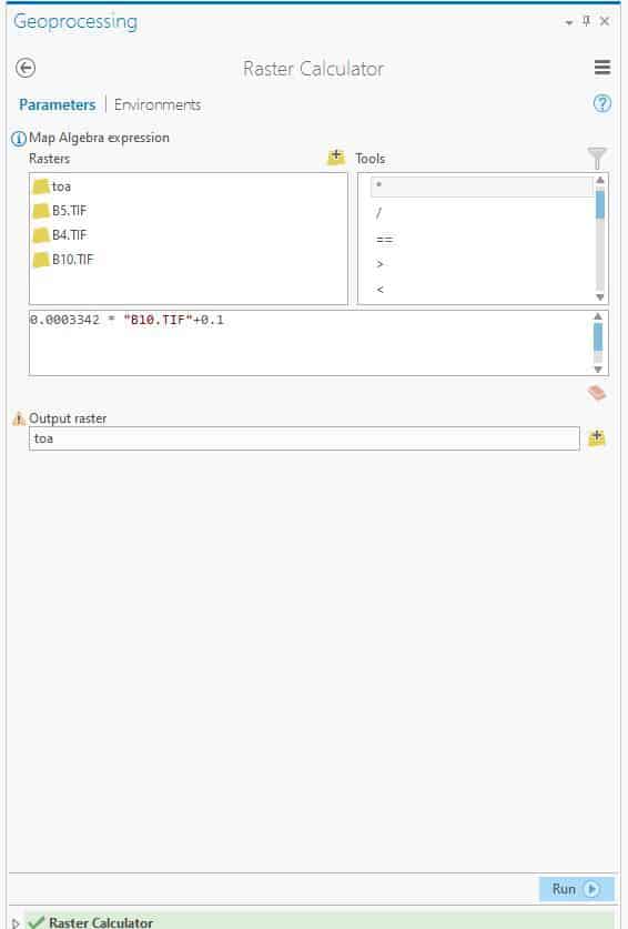
- Import band 10 onto the map canvas, using the “Add Data” tool. Set input location and name, and click “Open.”
- Type and search “raster calculator” from the search bar of the geoprocessing toolbox.
- Type the formula as illustrated in figure 5 below to calculate TOA from the band 10 imagery.
- Set output raster name and location, and click “Run.”
Note: “B10.tiff” as illustrated in figure 5 below represents band 10 of the Landsat 8 imagery.
Calculation of Brightness Temperature from TOA
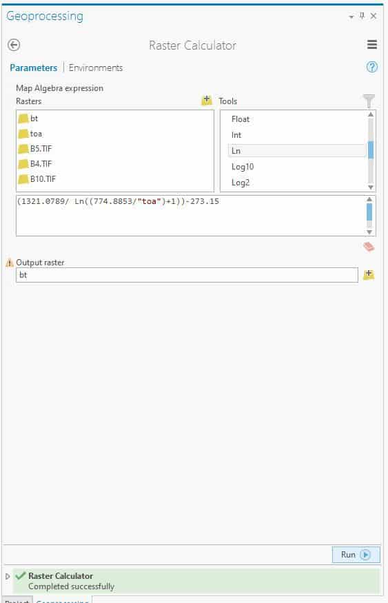
To calculate BT from TOA in ArcGIS Pro, follow the following steps;
- Type and search “raster calculator” from the search bar of the geoprocessing toolbox.
- Type the formula as illustrated in figure 6 below to calculate BT from TOA of the band 10 Landsat 8 imagery.
- Set output name and location, and click “Run.
Calculation of Proportion Vegetation Index (PVI) from NDVI

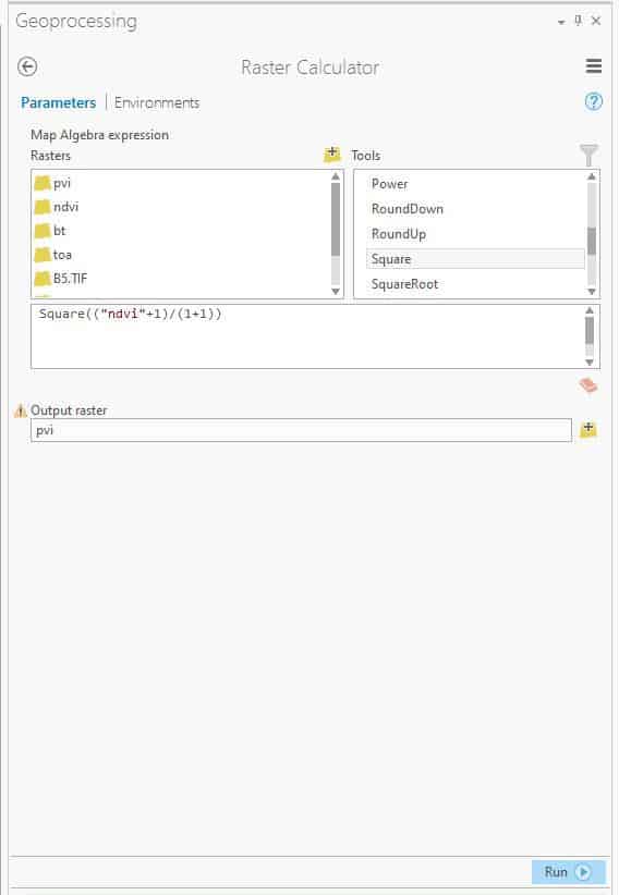
The following steps can be adhered to, in order to calculate PVI from NDVI;
- Type and search “raster calculator” from the search bar of the geoprocessing toolbox.
- Type the formula as shown below in figure 7 into the calculation bar of the raster calculator.
- Set output raster name and location, and click “Run.”
Note: “ndvi min” and “ndvi max” can be found in the “properties tab” of the NDVI layer.
Calculation of Error Correction (EC) from Proportional Vegetation Index
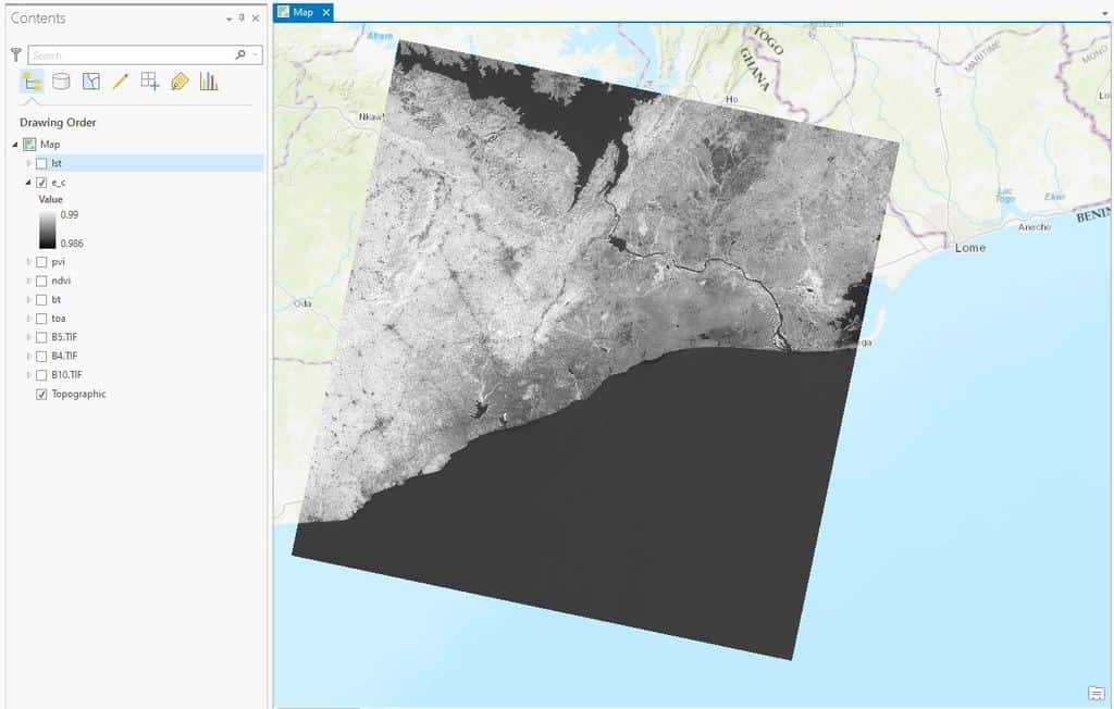
To perform error correction on proportional vegetation index of the Landsat 8 imagery, the following steps should be adhered to;
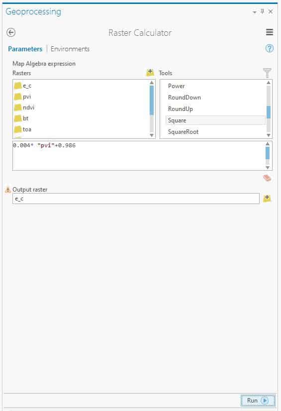
- Type and search “raster calculator” from the search bar of the geoprocessing toolbox.
- Type the formula as shown in figure 8 below into the search engine of the raster calculator.
- Set output name and location, and click “Run.”
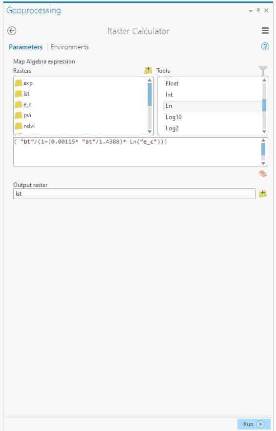
Calculation of Land Surface Temperature (LST)
To calculate Land LST from brightness temperature and error correction in ArcGIS Pro, the following steps can be followed. (Related: How to Use ArcGIS Pro to Calculate Land Surface Temperature (LST) from Landsat Imagery)
- Type and search “raster calculator” from the search bar of the geoprocessing toolbox.
- Type the formula as shown in figure 9 below into the search bar of the raster calculator.
- Set output raster name and location, and click “Run.”
Note: “e_c” and “bt” from the figure below represents the output of the error correction and brightness temperature calculation respectively.
Generation of Urban Heat Line and Stack Profile
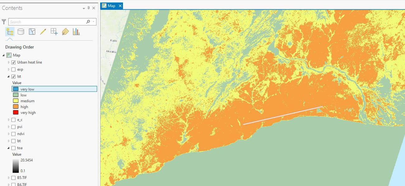
Urban heat line can be generated by creating a shapefile whilst setting the geometric feature to polyline. In other words, digitizing a line across any section of the output of the LST calculation.
For more information on creating feature classes on ArcGIS Pro, the following video may be helpful (https://www.youtube.com/watch?v=L2hmTvSEK0c).
Figure 10 below shows urban heat line that has been digitized and generated with respect to the Land Surface Temperature (LST) output.
After the generation of the urban heat line, stack profile of the heat line can be generated with respect to LST. The following steps outlined below can be used;
- Type and search “stack profile” from the search bar of the geoprocessing toolbox.
- Set input line features to urban heat line and target features to LST. Set name and location for output table. Click “Run.”
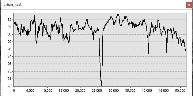
A graph can be generated from the “First_z” values which represents the temperature values in Degree Celsius generated by the urban areas across the urban heat line from the output table generated.
More ArcGIS Pro Tutorials
- How to Use ArcGIS Pro to Estimate Areas Prone to Malaria
- How to Use ArcGIS Pro to Calculate Land Surface Temperature (LST) from Landsat Imagery
- How to Use ArcGIS Pro to Assess Landslide Susceptibility
